Generating a clean Atari ST RGB C-Sync signal
Who didn't dream of plugging their old Atari ST on an LCD screen, and play to their favorites ST games ?
Although this was not as easy as one would expect, I eventually succeeded in having a nice and stable picture out of my Atari 520 STF on every RGB display devices I have.
I basically used a Lattice ICE40HX1K FPGA to generate a clean composite sync signal based on the H-Sync and V-Sync signals provided by the Atari ST.
The issue of plugging old machines on recent screens
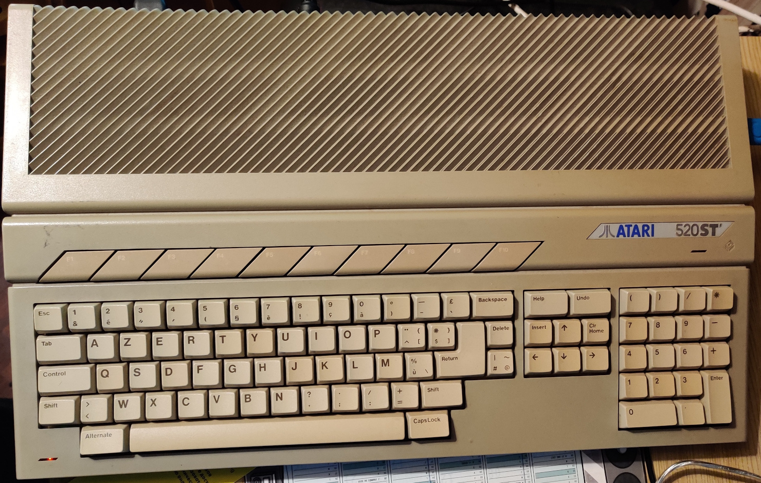
Computers and consoles from the 80's were meant to be used with devices from the same era; screens are no exception. Nonetheless, I tried to connect my Atari 520 STF to several monitors (or adapters) using an "Atari ST SCART" cable I could find online.
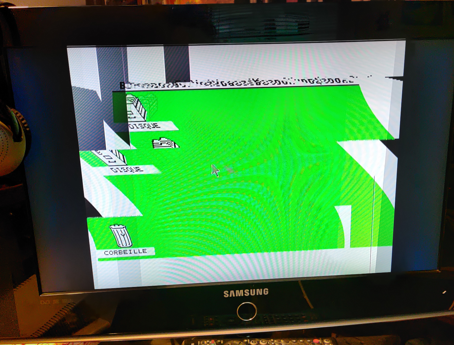
- On a Samsung LCD TV, I could see a rolling and distorted image, failing to synchronize;
- On a Phillips LCD TV, I could see a picture that would jump every second or so;
- On a cheap "HD Video Converter" (i.e SCART to HDMI upscaler) connected to a HDMI monitor, I got a black screen with a flickering picture every 2-3 seconds;
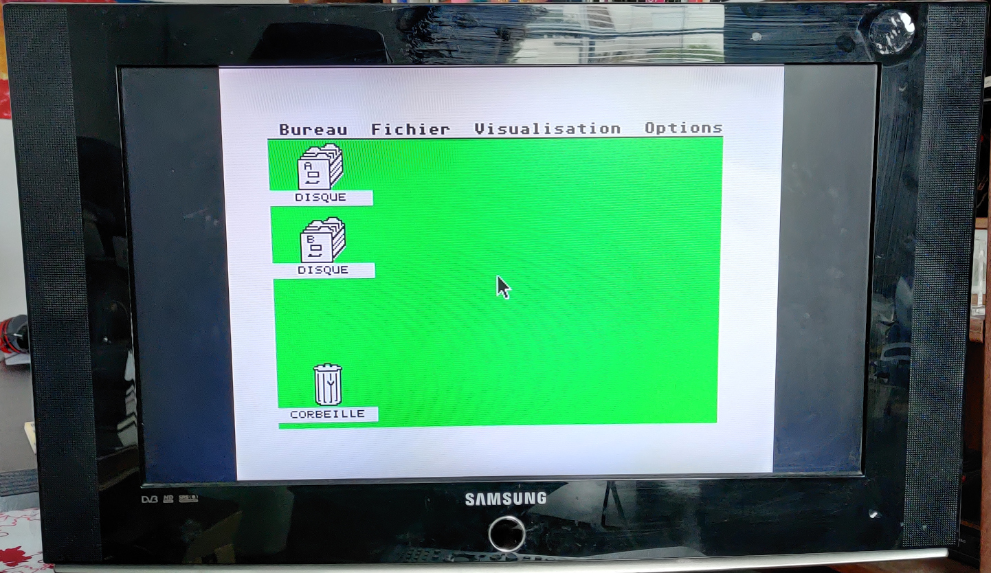
- On a Thomson cathode ray television from the 80's, I could get a nice, stable picture.
Score is 1/4 (failing on modern display hardware); not really satisfactory. Is the cable not good enough ? Or is it something deeper ? If so, how can we use our ancient machines with today's devices ?
There are actually devices like the Open Source Scan Converter that are "designed primarily for connecting retro video game consoles and home computers to modern displays". Though I like the idea, at the time of this writing, the OSSC has been out of stock for several months; and since I haven't tested it, I'm not 100% sure that it will work with my Atari STF.
So why not build our own cable / converter ?
Let's dig the issue
What does an Atari ST SCART cable looks like ?
The Atari ST SCART cable I received had a wiring pretty close to the one described by DrCoolZic in its Atari ST Interfaces & Connectors article. Here was my actual cable wiring:
|
|
Though this cable differs slightly from the DrCoolZic's, it works well with a cathode ray television:
- It uses the H-Sync signal instead of V-Sync for RGB selection,
- 120 Ohms resistors are used instead of 150 Ohms resistors for Red, Green and Blue signals,
- The ground is connected only to "Composite GND", instead of being connected to the ground of every signal.
Additional information about how to connect the Atari ST video output to an RGB capable monitor via SCART can be found from:
- the details of the SCART pinout (available on Wikipedia),
- and the Atari ST video connector pinout (on the Atari ST schematic).
The RGB selection signal
The first issue I encountered was with the RGB selection signal. According to Wikipedia's SCART page, the television expects on pin 16 (RGB selection or blanking signal) between 0 and 0.4 volts for a composite signal, and 1 to 3 volts for an RGB signal. Since the Atari ST outputs a RGB signal, we would expect a constant voltage between 1 and 3 volts on this pin.
H-Sync and V-Sync are 5 volts signals, high most of the time, and dropping to 0 volts to send horizontal (resp. vertical) synchronization pulses. Connecting H-Sync or V-Sync to the RGB selection pin works with the cathode ray monitor and the Samsung LCD TV (though there's another issue we'll handle later with this display), but not on the "HD Video Converter".
Fix is easy; disconnecting the H-Sync wire from the RGB selection pin on the SCART, then soldering a 1.5 or 1.2 volts battery (or a battery case for easy replacement / reloading of the battery) between the RGB selection (pin 16) and the Blanking signal ground (pin 18) solves the issue. Every display device now stays in RGB mode. This fix allows the "HD Video Converter" to display correctly the Atari STF video output on any HDMI screen.
Note that the battery has to power a 75 Ohms resistor connected to the RGB selection pin inside the monitor. A 1.2V rechargeable battery will generate a 16 milliamps current; with a standard capacity of 2800 mAh, it has to be reloaded every week.
Here's a French article describing more intrusive fixes for the same issue, without the need to use a battery. In the final design, we will set a 1.1V voltage on the RGB selection signal from a 3.3V supply.
The Composite Sync signal
The biggest issue (at least for my two LCD TVs) is the RGB composite sync (or C-Sync) signal emitted by the Atari ST. Although this signal was well handled by analog monitors, it doesn't play well with every digital devices. An interesting article about CSYNC engineering by HDRetrovision provides information about the C-Sync signal, especially describing what an ideal RGB synchronization signals look like.
Signals generated by the Atari STF
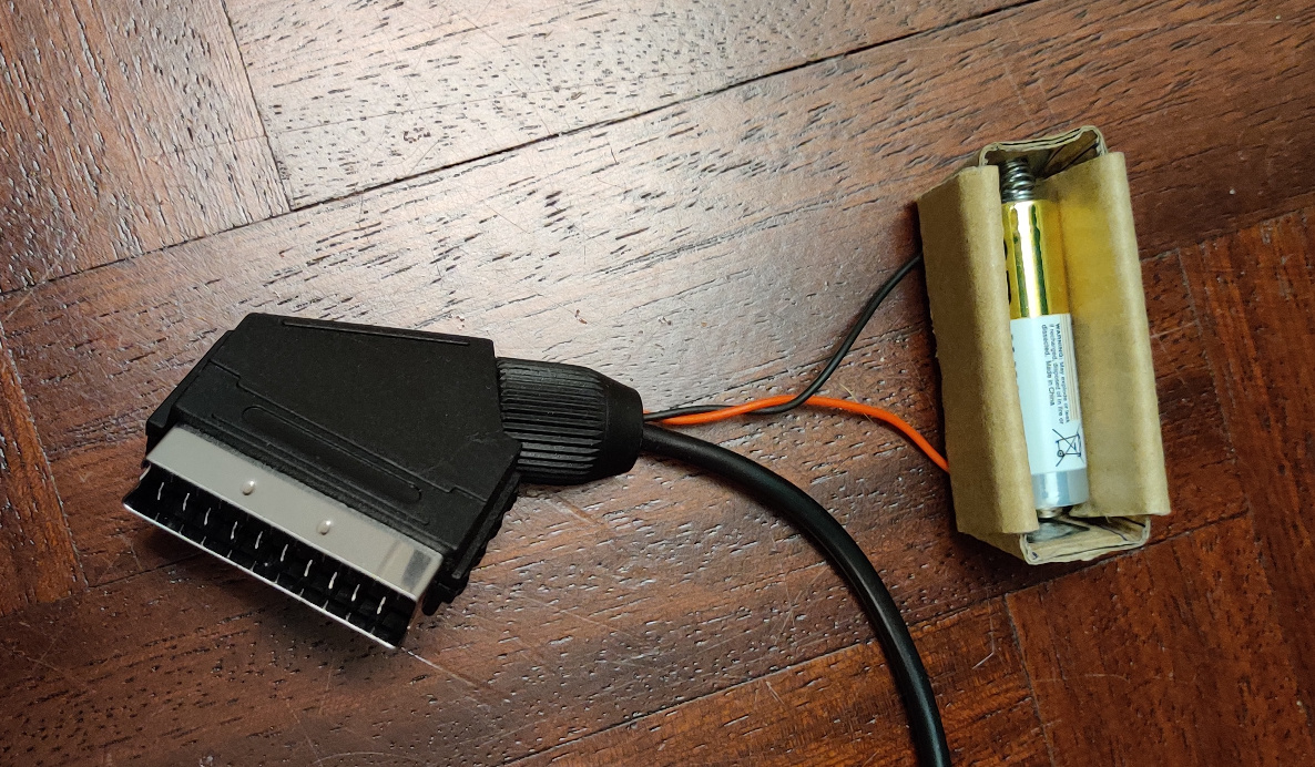
Let's have a look at the actual synchronization signals generated by the Atari 520 STF. For this, I'm using a Hantek 6022BL oscilloscope, with 2 probes, the blue one always triggering on the V-Sync falling edge, in order to compare signals on the same time frame.
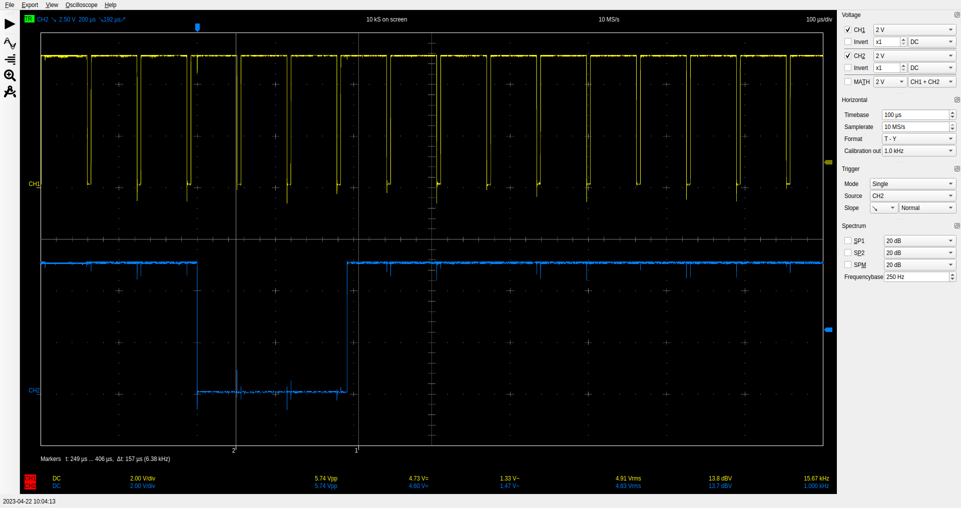
The H-Sync signal provides regular pulses, 5 microseconds long, at a frequency of 15.67 kilohertz. The V-Sync signal provides regular pulses, 191 microseconds long (i.e 3 lines long), at a frequency of 50.05 hertz. Moreover, if we look carefully, we can see that V-Sync and H-Sync falling edges are not synchronized. V-Sync falling edge happens roughly 13 microseconds after H-Sync falling edge.
The composite sync signal generated by the Atari ST is the logical AND between the H-Sync and V-Sync signals. This corroborates with the Atari ST schematic, page 3, "without modulator" block. The signal generated has a 3.5V high level and a 0.1V low level.
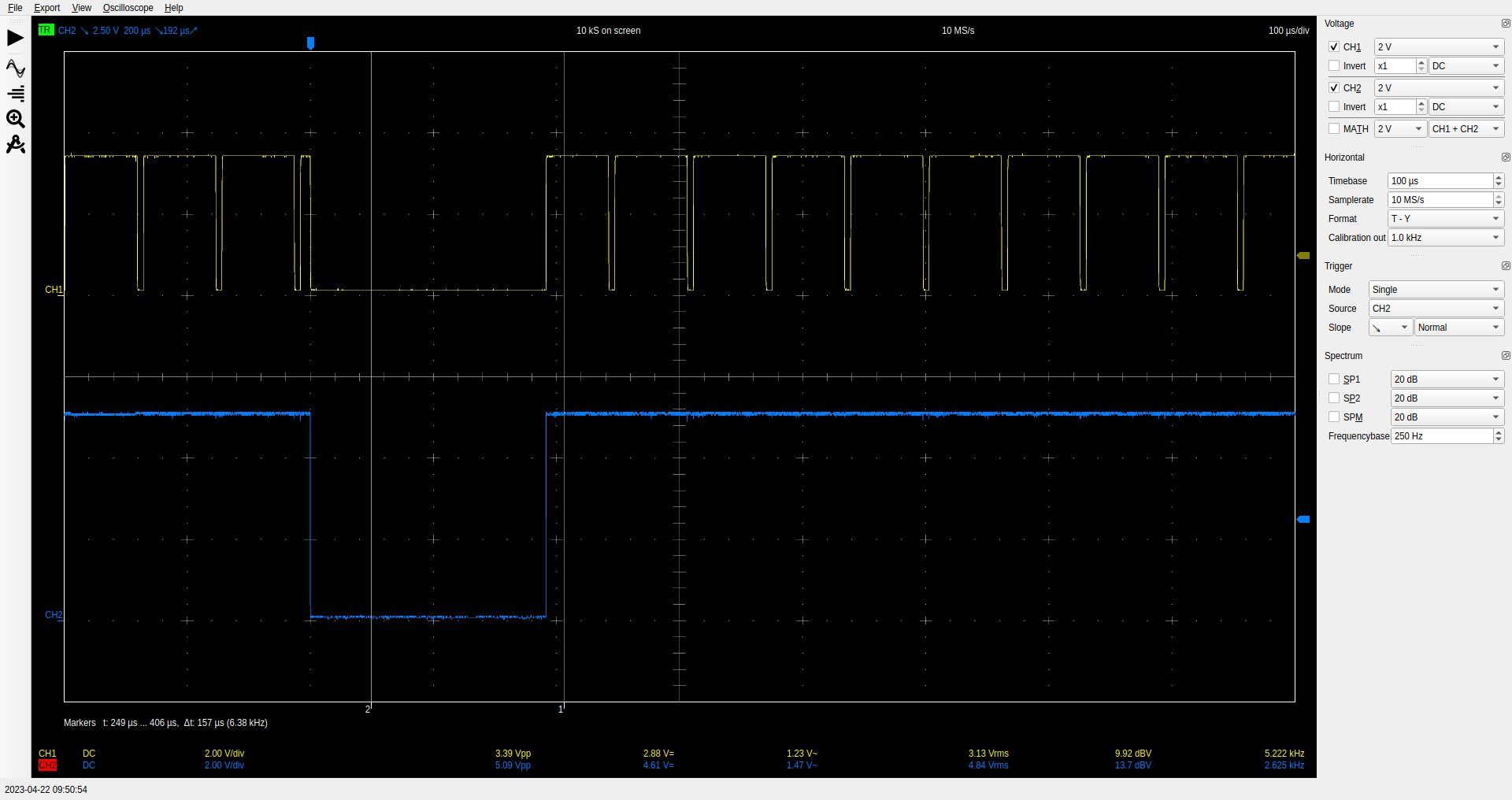
The composite sync signal (in yellow) generated by an FPGA matches the ideal composite sync signal described by HDRetrovision. It is synchronized with the H-Sync and V-Sync signals in real-time; and the voltage level has been adjusted to roughly 0.8V for high level and 0.15V for low level. It allows my Atari ST to display a stable picture on every RGB device I could test so far.
So how to generate perfect C-Sync ?
From what we've seen so far, the main issue is that the RGB composite sync signal generated by the Atari ST doesn't play well with most (recent) digital display devices; therefore, we need to adapt this composite sync signal to make it "compliant" with these devices. The idea of this project is to generate a clean RGB composite sync signal based on H-Sync and V-Sync provided by the Atari ST. For the prototype, I used a Lattice iCEstick Evaluation Kit embedding an ICE40HX-1K FPGA. The board is cheap, convenient, and the FPGA has a whole toolchain available as free / open source software running on Linux; from synthesizing the logical circuit, performing the placement and routing and programming the device.
Adapting signals voltage and current
In order to process the H-Sync and V-Sync signals from the Atari ST with our FPGA, then drive the composite sync pin of the TV, we need to make sure that the signals voltages and currents are compliant with every device (to avoid burning anything).
According to the iCEstick schematic diagrams, the iCE40HX1K I/O banks are powered at 3.3V; therefore, the FPGA is operating following the LVCMOS 3.3 standard. Under this mode of operations, the iCE40HX1K datasheet provides us with the following I/O signals voltage and current ranges:
- Low level (logical 0) input [min, max] voltage: [ -0.3 V , 0.8 V ]
- High level (logical 1) input [min, max] voltage: [ 2.0 V , 3.5 V ]
- Low level (logical 0) output [max voltage, max current]: [ 0.4 V , 8 mA ]
- High level (logical 1) output [min voltage, max current]: [ 2.9 V , 8 mA ]
- Input I/O leakage: += 10 uA
The H-Sync and V-Sync signals provided by the Atari ST are 5V signals; they need to be lowered around 3.3V to be used as FPGA inputs. We can achieve this with a simple voltage divider circuit. For the C-Sync output signal, we need to drive a 75 Ohms resistor (inside the TV) with a 0.7V voltage(*); this would draw a 9.34mA current from the FPGA, which is higher than the 8mA maximum specified by the datasheet. Therefore, we need to add a transistor to drive the output signal.
The following circuit adapts the input and output signals, so that everything plays nicely:
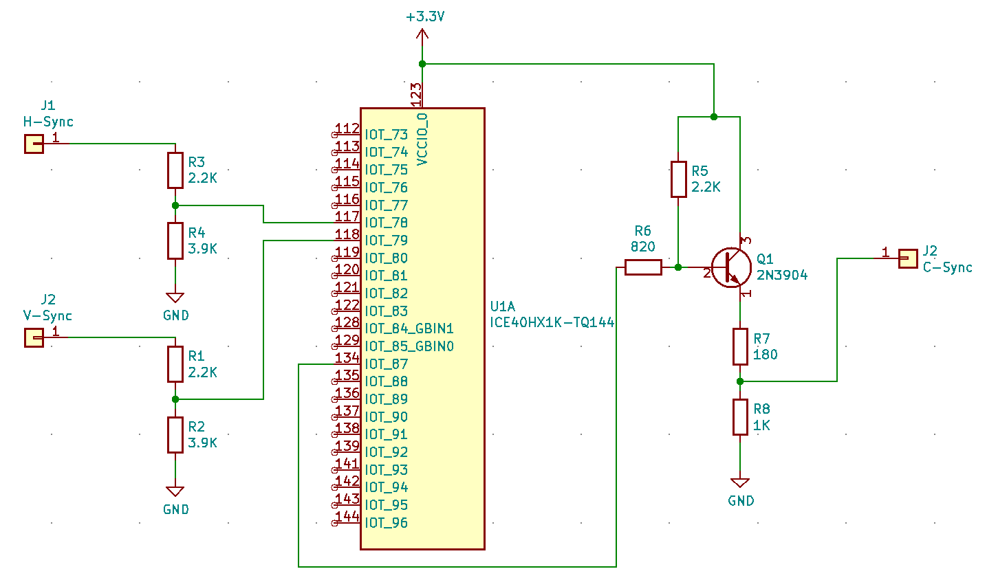
Let's have a quick look at our 5V H-sync and V-sync input (on the left). Each go through a 2.2 KOhms, then a 3.9 KOhms resistor. When high (logical 1), this creates a current of 0.8mA for each of these 2 signals, out of the Atari "Glue" chip, which is low enough. And the voltage on the FPGA pins is 3.2V; well within the [ 2.5V , 3.5V ] range.
On the C-Sync (output) side, the current going out of the FPGA pin is very small (lower than 0.1mA) when the signal is high (logical 1). The current dissipated by the FPGA when the signal is low (logical 0) is 1.1mA, which is lower than the 8mA allowed. When considering the 75 Ohms resistor in the display device, the C-Sync voltage is either 0.05V (low) or 0.76V (high). And the current going out the C-Sync pin is 10.2mA, complying with the transistor's specifications.
The signals emitted and received by every device (Atari ST, FPGA and LCD TV) are now within their specifications. We can now play with the FPGA and generate a signal that will allow the TV to display the Atari ST picture.
The FPGA code
The base idea is to keep track of time and generate a C-Sync signal with the following characteristics:
- C-Sync is high (logical 1) most of the time;
- with a 191.5 us pulse (low level / logical 0) 50.05 times per second (every 19.98 ms), corresponding to 3 lines out of 313 every frame, for the vertical synchronization;
- and a falling edge for 5 us, 15670 times per second (every 63.8 us), for the horizontal synchronization (also during the vertical synchronization pulse).
In order to generate such signal, we need to keep 2 counters: a dot / pixel counter, that will allow us to generate the H-Sync falling edge every 19.98 us, and a line counter to generate the V-Sync pulse 3 lines out of 313, while still generating the H-Sync falling edge every 19.98 us.
Here's what the counters look like in verilog:
    if (dot_cnt == LINE_TICKS-1) // End of line reached
      begin
         dot_cnt <= 0;
         if (line_cnt == FRAME_LINES-1) // End of frame
           line_cnt <= 0;
         else
           line_cnt <= line_cnt + 1;
      end
    else
      dot_cnt <= dot_cnt + 1;
And how we generate our C-Sync output according to our 2 counters:
    if (dot_cnt < HSYNC_HIGH_DOT)
      if (line_cnt < FRAME_LINES - 3) // on 2 last lines vsync is low
        creg <= 1;
      else // Max line_cnt value is FRAME_LINES-1
        creg <= 0;
    else
      if (dot_cnt < HSYNC_LOW_DOT)
        creg <= 1;
      else
        creg <= 0;
Finally, we need to synchronize our generated signal with the H-Sync and V-Sync signals, to keep the C-Sync output in sync with the RGB signals sent by the Atari ST:
    if (vpulse)
      line_cnt <= 0; // Resynchronize on vpulse
    if (hpulse)
      // Resynchronize on hpulse to avoid drift. We're a few ticks
      // into hsync_low when we see the pulse.
      dot_cnt <= HSYNC_LOW_DOT + 5 ;
The full FPGA code is available on github.
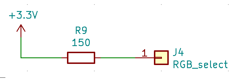
Replacing the 1.2V battery
Now that we have a 3.3V source, let's replace this silly battery. A simple 150 Ohms resistor allows us to feed the TV RGB selection pin with a steady 1.1V at 15 mA.
The End
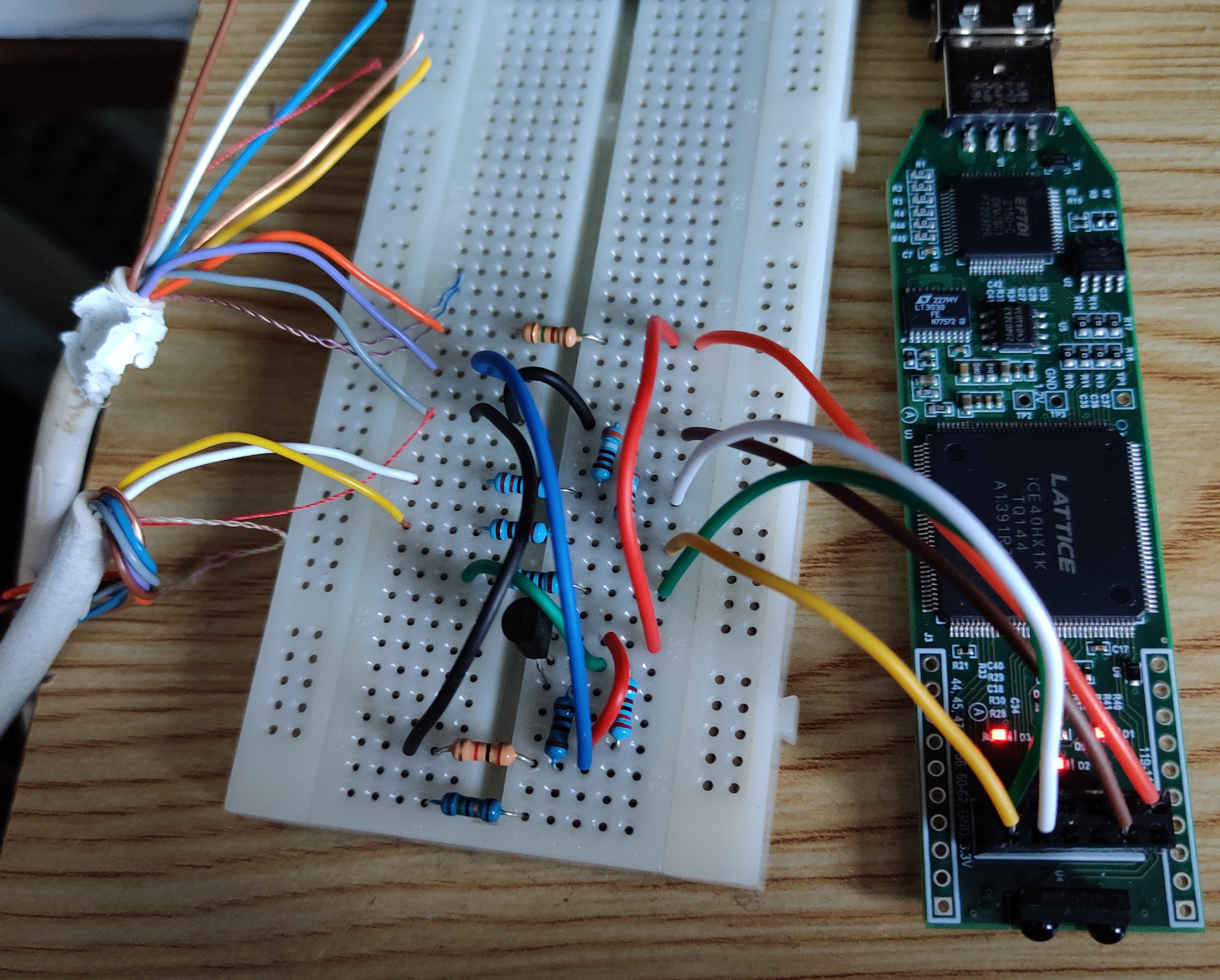
If you succeeded in reading the whole article, congratulations ! Here's a little picture of the C-Sync signal generator prototype:
(*) I couldn't find any official specifications for the voltage of the C-Sync signal, but some websites mention 0.7V, while others say 1V.