2-resistors MIDI interface
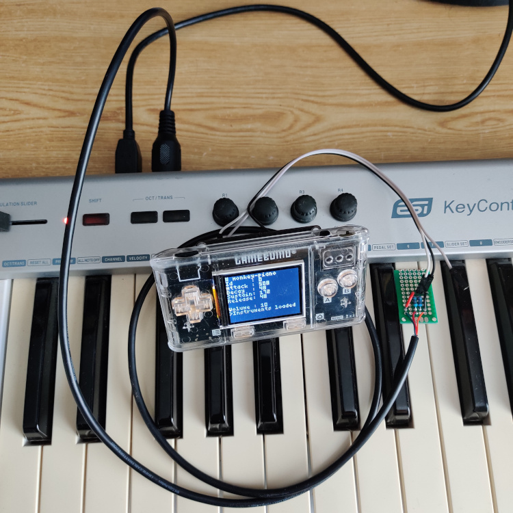
I've been playing with my digital piano once a while; although it has a few instruments, I felt I could use its midi output to play sounds from the 80's generated by a software synthesizer I could write, running on some cheap microcontroller. I eventually implemented a basic synthesizer for the Gamebuino, a little console embedding a Microchip SAMD21 microcontroller, with a 32 bits ARM Cortex M0+ CPU, 256 KB of flash and 32 KB of RAM. The console is conveniently shipped with a development interface exposing USART pins, an audio output jack, a battery, a TFT screen, a micro SD card drive and a few buttons. This article will focus on the midi interface; i.e how to connect a midi keyboard to a microcontroller (or a computer).
The MIDI interface
My journey started with the MIDI Wikipedia article, which technical specifications say:
MIDI messages are made up of 8-bit bytes transmitted at 31,250 baud using 8-N-1 asynchronous serial communication.
This means that we can basically connect a wire from an instrument's midi output to a computer's UART, configured as specified above, and see the messages flow. That's actually correct, after having somehow adapted the signal.
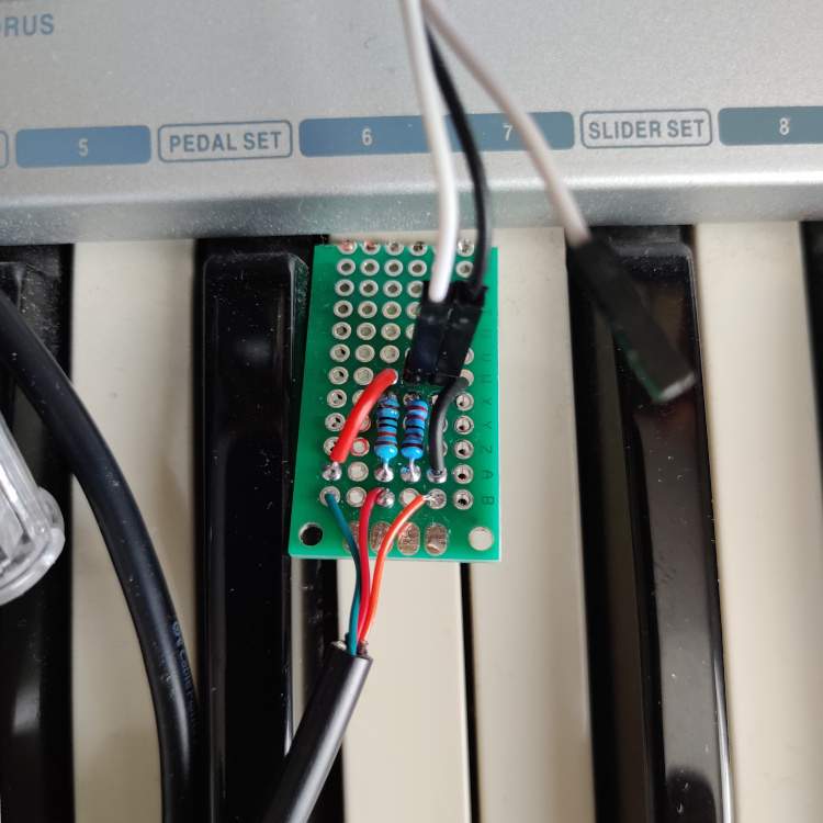
The electrical specifications are a good starting point. Since I didn't have an opto-isolator at hand, I decided to try to use a bunch of resistors instead. The opto-isolators are meant to electrically isolate the devices, but I decided to give it a try without this refinement for a first prototype.
A schematic of a 2-resistors midi interface is depicted below. On the left side, 3 wires are connected to the instrument's midi output: Vcc, Din and GND. On the right side, 2 wires are connected to the microcontroller: Dout and GND. The grounds of the 2 devices are connected together.

The instrument's midi signal is transmitted by the Din wire. The current flows from the instrument's Vcc wire, either to its Din wire or GND, depending on Din's state. When Din is open, Dout = 2/3Vcc, when Din is connected to GND, Dout = 0V.
On one of my keyboards Vcc = 5V, on another Vcc = 3.3V. This means that Dout high-level will be either 3.44V or 2.27V. Both values are in the [1.82; 3.90]V range of the SAMD21 microcontroller's acceptable input high-level voltage, for 3.3V VDD, according to its datasheet.
The picture below shows the front view of a MIDI 5-pins DIN connector, as seen in front of the connector (with the pins towards your eyes). Pins 2, 4, and 5 carry signals GND, Vcc and Din respectively.

|
|
While the DIN connector is plugged into the instrument's midi output, the Dout wire needs to be connected to the microcontroller's UART RX pin and GND to its ground (see schematic above). Et voilà, notes played on the MIDI keyboard merryly flow to the microcontroller, who can play the corresponding square waves.
 |
 |